1.
 |
3.
 |
4.
 |
5.
 |
7.

|
2.
 |
6.
 |
8.
 |
9.
 |
11.

|
13.
 |
15.
 |
16.
 |
10.
 |
12.
 |
14.

|
Explanations for each
picture are below.
|
17.
 |
19.
 |
21.

|
23.
 |
25.
 |
18.
 |
20.

|
22.
 |
24.
 |
Click on any picture to
link to a larger image.
|
26.
 |
28.
 |
29.
 |
31.
 |
32.
 |
27.
 |
30.
 |
|
|
| 1. The diver's hatch is shaped from a block
of RenShape material. |
| 2. The hull curve is lofted from the area of
the diver's hatch using five layers of 7oz fiberglass cloth, the
RenShape block carved to fit, and a master "puck" made from
which to vacuum form the actual hatch. |
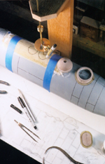
| 3. The drop-pen compass is used again to mark
the circumference of the main hatch on layers of fiberglass clothe which
will serve as the flange around the conning tower. |
| 4. Note the conning tower in foreground. This
was created from RenShape on a lathe and hollowed out to the final
diameter. |
| 5. Details of drop-pen compass and main hatch
flange after removal from hull. |
| 6. Tools used to trim and shape the
fiberglass flange. |
| 7. Fitting the conning tower combing to the
hull . . . |
| 8. . . . and the dome. |
| 9. Port hole flanges for the conning tower
were turned on a lathe and, with the brass piece still in the chuck,
holes drilled to later accept rivets. |
| 10. Returned to the lathe, the porthole
flanges are parted into individual pieces. |
| 11. Parts of the diver's and main hatch and
conning tower before assembly. |
| 12. Main hatch. |
| 13. Preparing the propeller shaft for the
process of creating the shaft and blades and mounting on the hull. This
shaft is one of the conjectural elements on the Alligator model. The
1861 version, of course, had no propeller since it used oars for
propulsion. During the 1862/63 refit, the propeller was added--but were
the rudders moved to accommodate it or was the shaft extended beyond the
rudder? Adding a propeller extension seems the simplest solution . . . |
| 14. After alignment, the prop shaft is
pressed against the stern with carbon paper sandwiched in between to
show any points that do not align. |
| 15. Diagram of the propeller shaft and rough
pieces of the propeller blades. |
| 16. Final prop blade is mounted vertically
and the mold container set over it (clear cylinder to right) and sealed
with clay. Silicon rubber is poured in and allowed to solidify. |
| 17. After removing master blade by slicing
the mold along its vertical sides, the mold is resealed with rubber
bands, and Alumilite resin is poured into the cavity through the prop
shaft that had been allowed to protrude through one end of the mold.
Also shown are a number of the poured blades. |
| 18. Prop blades are mounted onto the hub at
identical angles by affixing each one to the shaft while it lies atop a
bed of clay. |
| 19 & 20. Views of the final propeller and
shaft. |
| 21. Mounting the final propeller and shaft
onto the hull. |
| 22. Figures, hatches, portholes, propeller,
and rudders. |
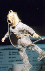
| 23. Plans and parts for the diver's helmet. |
| 24. Diver and helmet parts. |
| 25. Final helmet. This is the Miller-Dunn
style helmet, which is not evidenced officially until after the Civil
War. The standard deep sea diver Siebe helmet would have been too large
and cumbersome for the diver to have used in moving through the hatch.
Another alternative is a leather helmet first created in Paris for
firemen to use in smoky buildings; de Villeroi may have been aware of
it. The US Navy also experimented with a leather diving helmet, but,
officially, not until 1863. |
| 26-30. Views of the diver as he nears
completion. Married to the air hose is the lifeline that anchors the
diver to the submarine. |
| 31 & 32. Marking out the buoyancy tanks
with the drop-pen compass. |

